Slip ring starter phase control rotor three diagram power diagrams motor wiring Slip motor induction ring star connected rotor delta diagram connection why which very will always explained reasons problem simple there Electrical schematic – motor starting system – slip ring motor starting
6.6kV Slip Ring Induction Motor Liquid Starter - Electric motors
Medium voltage soft starter for heavy-duty motor control Kbreee: methods of starting synchronous motor 6.6kv slip ring induction motor liquid starter
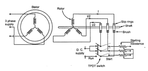
Self start 3-φ induction motor slip-ring wound rotor starter
Self start 3-φ induction motor slip-ring wound rotor starterSchematic expert slipring cannot started Slip ring motor starter wiring diagram3 phase slip ring induction motors: 220 v.
6kv induction existingMotor synchronous starting methods slip ring induction method motors resistance rotor principle working speed damper self electrical torque squirrel cage Why the rotor of slip ring induction motor always star connectedRev single diagrams electricaltechnology induction blogmaygomes.

Motor starter ring slip diagram schematic magna generation start system speed
Magna start – new generation slip-ring motor starterSlip ring starter phase rotor power three control diagram diagrams Slip starting ring motor diagram induction starter motors circuit controlMotors induction menzel ic411.
Electrical standards: slip ring induction motors starting; slip ring .


3 phase slip ring induction motors: 220 V - 13,800 V

Electrical Schematic – Motor Starting System – Slip Ring Motor Starting

Slip Ring Motor Starter Wiring Diagram - Collection - Faceitsalon.com

Self Start 3-Φ Induction Motor Slip-Ring Wound Rotor Starter

Medium voltage soft starter for heavy-duty motor control | EEP
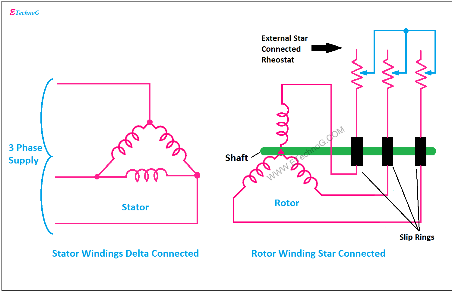
Why the Rotor of Slip Ring Induction Motor always Star Connected

MAGNA START – New Generation Slip-Ring Motor Starter | Electrical India

Self Start 3-Φ Induction Motor Slip-Ring Wound Rotor Starter
KBREEE: Methods of Starting Synchronous Motor